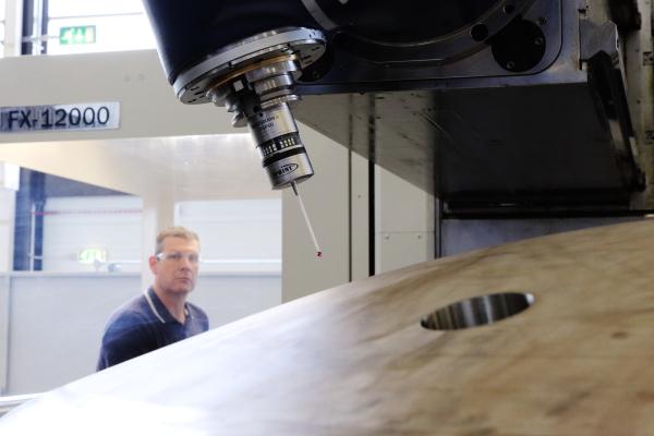
If you’re designing a new product or component, considering the requirements for inspection can improve productivity and boost quality. Carl Hitchens, Nuclear AMRC head of machining and metrology, introduces the essentials of design for inspection.
When designing new products or components, it is now common practice to use design for manufacturability (DFM) techniques to minimise production costs and increase efficiency.
DFM is essentially about designing products so that they’re efficient to manufacture, by identifying the key manufacturing processes early on, and factoring them into the design specification. As a simple example, increasing the radius of a feature to facilitate machining can reduce time and tooling costs.
To complement this approach, engineers have also developed design for assembly (DFA) techniques. The driving principles here include reducing the part count, and using self-locating components and single orientation assembly.
One area that is frequently overlooked at the design stage is inspection, which can impose significant costs later in the manufacturing process. I have campaigned on design for inspection (DFI) for many years, creating the Wikipedia page on DFI and promoting new thinking in the area.
The DFI principle proposes that the inspection methods and measurement instruments used to certify component and product conformity should be considered early in the design process, in the same way as DFM and DFA are currently considered. It also aims to reduce costs by applying knowledge of the fundamental principles of metrology.
The role of inspection in the manufacturing process is to ensure we are producing components that meet the specification requirements. Obviously, inspection by itself does not assure the quality and conformity. You can’t inspect these attributes in – they have to be controlled by robust manufacturing processes.
If you consider and select the inspection method and instruments at the design stage, you can substantially reduce the risk that a tolerance feature cannot be inspected or requires a specialised instrument. High-precision features require specialised manufacturing and metrology, which can add cost and limit the choice of suppliers.
DFI will not always reduce inspection costs or the need for inspection – inspection is always necessary. It may, however, allow you to increase the rate of inspection, because more convenient or higher quality measurements are possible.
DFI may enable a sampling rate of 100 per cent, allowing you to minimise the risk of product recalls. This increase in inspection could be justified if offset against the cost of rework and failure, and can provide an increased reputation for quality in the market – we all want reliable high-quality products, and customers are often willing to pay more for these.
Below, I introduce the key areas for DFI, with some questions and comments to consider for any new component.

Datum
- Can the datum as defined in the design be easily established on the component, in terms of access?
- Is the feature selected on the component of sufficient area to create a stable datum, especially if the datum is projected over a distance?
- Will the surface roughness and finish introduce uncertainty in establishing the datum?
- Is the datum appropriate for component function, and also for the inspection method and available measurement instruments?
- Can the component design incorporate features to assist datum definition?
- Fixture points, such as centres created at the time of manufacture, can greatly assist the measurement process. Designed points will help manage deflection which can substantially influence measurement results, and enable more consistent measurement.
Tolerances
- Set the tolerance of components based on the uncertainty of the measurement system. Consider the 10 per cent rule, that states that the uncertainty should not account for more than 10 per cent of the available tolerance.
- If a high precision of tolerance is essential for the function of a component, consider if a suitable measurement instrument is available for the specified feature tolerance.
- If the feature is not functional, can the tolerance be relaxed?
- Tolerances which are remote from their datum feature will inherently have additional uncertainty – should you use an additional datum?
- Select tolerances to simplify inspection, avoiding measures which require specialist equipment or are difficult to apply. For example, symmetry tolerances are time-consuming and difficult; concentricity tolerances can be more easily inspected using position and run-out tolerances; profile tolerances are challenging if not accessible or visible.
Accessibility
- Can instruments access the feature? Consider how hand tools will be deployed, and the available lengths of stylus.
- Will restricted access add to the uncertainty of the measurement system?
- Should we tolerance features that cannot be inspected? Aspirational tolerances are a constant source of concern for manufacturers and inspectors.
Other considerations
- Use in-process inspection where practicable.
- Avoid repeated inspection – pass off features in the process, and only visually inspect for damage at final inspection.
- Establishing the true value of partial arcs less than 90 degrees can be challenging.
- Large dimensions with tight tolerances are often outside the capability measurement instruments.
- Projected tolerances over substantial distance are difficult to measure and have a high uncertainty.
- A smooth surface can improve measurement consistency, but will increase the cost of manufacture. Select regions to apply higher surface finishes for inspection and datum construction.
- For coated components, should you inspect before or after coating? Consider the process control of the depth of coating, and how this might impact on the inspection process.
- How susceptible are the component and measurement system to environmental change?


